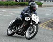
Summary of development work
Rather than trying to visually compare inlet ports, we found it best to compare by measuring capacity with valve fitted in cc's using a burette, several engines that were down for power were found to be smaller capacity; 136cc instead of 148cc on an A7 twin, a B34 GS port 117cc extension 128 total induction 245cc.
All bench tests were carried out in uniform manner starting at lowest practical RPM and going up in increments of 250 RPM with no pause. Flash readings were never reported. We did try running power curves in reverse order starting at maximum revs and coming down but decided this gave false high readings.
Sandilands discovered almost by accident that a venturi shape after the carburettor can be 85% of the area of the carburettor body area with no loss of power, in fact it gave a small increase. We did most of our power curves with a flow meter hooked up between fuel tank and carburettor, this gives a valuable check on efficiency and also on correct carburettor settings.
When using two into one exhaust system it is desirable to have each pipe from the cylinder head to the junction of equal length if not carburation may be drastically affected at some point in the range. The way to avoid this problem is to ensure that each pipe has the same length to area ratio, in other words the longer piece will be larger diameter. In our experiments with the short stroke 500cc A7 twin we also found the angle of the two pipes at their intersection was important. I was at MIRA once waiting to use the timing strip whilst a group of Royal Enfield people tried to get the carburation right on one of the 700cc twins fitted with a two into one exhaust system, I noticed they were using the same diameter exhaust pipes of different lengths before the junction. Strangely enough this same rule holds good for induction pipes as found by Guzzi on their later single cylinder racers.
The A7 and A10 connecting rod bolts were originally BSF threads, we changed this to 26 threads per inch cycle threads as we thought larger area at the root of the thread would make a stronger bolt, we had to reduce torque when tightening the big end nuts proportionally, unfortunately someone in the drawing office forgot to tell the engine assembly and several bolts were broken before the error was discovered. Even more strange was the fact the broken bolts only happened to one of the several mechanics assembling the crank assemblies. I was asked to investigate, so sent Arthur Butler up to the engine assembly to watch how they did this torquing up. He returned a little later laughing with a small tobacco tin in his hand, It had plumbers tallow in it, apparently only one mechanic was putting tallow on the threads before tightening, with the results that nuts tightened appreciably more before the torque wrench recorded the correct torque figures. We accordingly tested some bolts with various lubricants on the thread and decided that important bolts such as connecting rod bolts should be assembled clean.
Oil Pumps.The BSA gear type pump is very simple and reliable, at one time we did some tests by simply running a pump on a drill press in a can of oil and measuring the temperature of the oil, we were surprised at how quickly the temperature rose especially as there was not resistance to the flow. On examination of the pump we decided that some oil was being compressed between the two gears, accordingly a small bypass was cut in the cover plate allowing oil to feed back to the inlet side of the pump. Further testing showed practically no heat build up in the oil. Some tests were carried out on A7 (using various viscosity oils, starting with 50 wt and coming down to 40 wt to 30 wt, 20 wt SAE 10 and finally 5 wt. We discovered that normal oil pressure was maintained on the SAE 10 50 wt, 40 wt and 30 wt. At SAE 20 viscosity pressure tended to drop particularly when hot. The engine was stripped at this point to see if the low pressure caused any bearing problems, everything looked pretty good. At SAE 10 wt pressure seemed very low in fact when hot was nil a further examination of the bearings and pistons showed no sign of trouble but the cam followers did not look too happy, starting to score.
A final run was made with SAE 5 wt pressure almost nil when cold, showed nil when hot especially when engine was revved up, finally the timing side main bearing failed. On stripping the engine we found the white metal had melted and run, but no trace of it in the oil or crankcase, when the sealing plugs were removed from the crankshaft the white metal, was found to be inside the oil passages of the crankshaft, the connecting rod bearings appeared to be in good condition. Apparently the light 5 wt oil was thrown outwards to the big end bearings by centrifugal force enough to lubricate the big end bearings adequately but in such quantity that it robbed oil from the main bearings faster than the oil pump could replace it.
One interesting test was when we set up a A10 engine and gearbox unit on the test bed driving the dyno by a short chain, the object was to try and measure the power loss in the gearbox in each gear. We could not measure the power in 1st gear as the dyno was turning too slowly to absorb the considerable torque due to the low gear ratio. As we expected the most efficient gear was 4th, the direct gear.
Surprisingly, 2nd gear was more efficient than 3rd gear due presumably to the fact that 2nd gear wheels were better supported than 3rd. The final part of the test was when we removed the gearbox and clutch and tried to run a fairly long chain from the engine to the dyno direct to see what difference was with gearbox out of action. To our surprise it could not be done, this rather long chain just whipped and banged and would not transmit power. We had to move the engine back on the block and used a short chain. Incidentally the power loss in 3rd gear was about 10% with about 8% loss in 2nd gear as compared with 4th gear with only 2%. One of the lesser known advantages of the eccentric rocker spindles is the ability to adjust the valves whilst the engine is running.
I suggested this to Reg Wilkes one day, however, he did not seem very keen to stand astride a high revving engine with a wrench in either hand so I appointed myself as the rocker manipulator. We started off on the 500 Gold Star race engine at about 5000 rpm with me firmly astride and adjusted each rocker until the maximum power reading was obtained. The engine was then blown cool with the fan and clearance checked, the inlet figure was something like .009" and exhaust a little more. Then the engine was run at 6000rpm and again rockers adjusted for maximum power and cooled down to room temperature and clearances checked, this time the inlet was .006" and exhaust .008".
Next a reading was taken at 6500 rpm and again clearances checked when cool. Now the inlet clearance was down to about .003" and exhaust .006", subsequent checks were made at 7000 rpm and 7500, with some pointed remarks made about what happened to me if the engine shuld blow up while I am astride it. The results at 7000 rpm were clearances Inlet .001" Exhaust .004" at 7500 rpm inlet nil, exhaust clearances .003". These were not exact figures (my memory is not that good) but the general trend was there at the higher revolutions the rockers and push rods were bending and whipping slightly.
Prior to these tests we had always set valve clearances with a cold engine, with inlet push rod just free to rotate and .003" clearance on the exhaust. The normal practice with regard to rocker angle in relation to valve stem has been to arrange for the rocker to be at right angles to the valve stem at half lift, the object being to minimise side thrust and cut down on valve guide wear. In the course of experiments with both the C12 and the A7 engine better running at high revolutions could be obtained when the rocker was at right angles to the valve stem at about l/32"to 1/16" lift. It was thought that this arrangement aligned the valve seat with the valve seat in the head just as the valve was closing, whereas with the common setting at half lift, the rocker side thrust will tip the valve slightly in the guide when seating and will have to realign itself as it seats. At very high revolutions there is not enough time for this and some efficiency will be lost. On the C12 this was visible even by turning the engine by hand, by inserting some packing between the rocker mounts and the head we were able to see the improved action. It is quite possible that most overhead valve engines using rockers could benefit from this rearrangement of rocker angles.
One unexpected results when trying a much larger and stiffer crankpin with plain bearing was considerable difficulty in lining up the flywheel assembly, presumably the wider shoulders made the assembly more rigid. Engine gaskets between rocker box and cylinder head usually made of paper were replaced with metal corrugated gaskets, these could be used over and over again and sealed better.
During the five years I was at BSA doing engine development I was fortunate in attracting some very bright and enthusiastic mechanics and apprentices, they all contributed to the progress we made with development of the BSA range. There was tendency to specialise but most could handle anything that came in the shop. Jimmy Gibbard did most of the odd machinery jobs, Jack Turner did the intricate inlet port arrangements and exploited the extra down draft angles and straight ports. Reg Wilkes, Bert Hole, Arthur Butler, Arthur Bridgewood, Bill Bently and Alan Sandilands could handle any aspect of engine building , the apprentices who spent more than average time with us were Gordon Smith, Robert Trigg, Ray Beech, David Harris and John Taft. Albert Dyde, ??? Harrison Ward and Hill came into the shop later. We also had some colonials like Barry Stormont and Cohn Mather during the winter months. I learned a great deal and was able to try out many ideas that I could never have done in the ordinary way, for this I am grateful to Mr Hopwood and BSA for this opportunity.
One of the chief abilities necessary in this type of work is to be able to 'sell' ideas to the Management, something I was not very good at. Thanks to BSA sending me to the USA on business trips I decided to emigrate and have had an interesting life in USA becoming a citizen in 1982, finally having my own business and a and a decent workshop including a dynomometer. I have not lost interest in motorcycles and at 75 own a 250cc Kawasaki 'Ninja', a remarkable little machine with a performance in road trim better than my old racers. We still enjoy trips to Road Atlanta to watch the motor cycle road each year.
Showing posts with label Alan Sandilands. Show all posts
Showing posts with label Alan Sandilands. Show all posts
Monday, 9 February 2009


Sunday, 25 January 2009
Roland Pike Autobiography - Chapter 23
The development of my favourite the Gold Star.
When I came to work at BSA in 1952 there was no programme of development for the Gold Star, at that time we seemed to just pick up problems as they developed and try to fix them. The 350 Gold Star did quite well in the Clubmans TT, their power output averaged 27 to 28bhp. There were a number of problems causing retirements in the races the most serious of these was the heads burning near the joint face. Cyril Halliburn who was my assistant in those days suggested it was the porous castings and wanted to blame the foundry, strangely, the foundry did not deny this but said they did not understand what was wrong. In the Isle of Man during the practice period several of the heads were discovered to be 'burnt' when removed for examination. My opinion was that the joint at the Back to top of the cylinder barrel and head left an annular gap varying from .005" to .035", the wider joints trapped some gas which detonated causing the burnt heads. The normal gasket was a fairly thick copper asbestos affair, the production people claimed an inability to hold tolerances on cylinder barrel spigot and cylinder head spigot joint to less than .015", the gaskets also varied in thickness. It must be remembered that this gasket also had to make an oil tight joint at push rod tunnel. My solution was to use a ‘Plexseal’ joint, this gasket was formed of aluminium foil .002" thick stuck together to form a laminated gasket whose thickness could be varied by peeling off a layer one at a time to get a perfect joint, keeping the annular joint gap to between zero and .002" and yet still sealing the push rod tunnel. My suggestion was accepted but it did not reach production until later in 1952 or early 1953.
Another quite serious problem was the crankcase breather, situated in the timing case. A small pen steel disc acted as an automatic flap valve, unfortunately it did not work efficiently if at all at high speeds, thus allowing a lot of engine oil to blow out of the crankcase. Some of the riders ran out of oil due to this, all complained of the oil all over the rear tyre. My solution was to build a rotating sleeve in the timing cover driven by a peg on the magneto pinion, this was made in time for our testing at Montlhery in 1953. This mechanical breather was very successful as it kept the pressure in the crankcase about 4" - 7" below atmosphere at all speeds, which kept the oil in the engine and rear tire cleaner. Surprisingly this breather contributed a slight increase in power of 4bhp over the flap valve. The best timing was for the port to open 20 degrees before BDC on each stroke. Another problem was the occasional exhaust valve breakage which usually did quite a bit of damage.
The Research dept came up with the answer here. A special nickel alloy Nimonic 80, after its use I never saw another one break. A difficult problem was valve springs. I would have liked to have gone to hairpin springs but this was not possible. We tried all the usual approaches, talking to Terry's, the spring experts, even our friends at Rover designed a spring to try, our own spring shop tried various tricks and materials but we were getting very little progress, then Hap Alzina sent some S&W springs for the twins, I decided to try these in a Gold Star and they worked beautifully right from the start, giving us a big increase in maximum revs. I suspected shorter connecting rods might show some advantages in several ways, firstly by changing piston motion relative to crankshaft rotation, also shortening the whole engine including the push rods.. We built some 350 engines using A10 and A7 connecting rods, these showed an appreciable increase in performance but we could not be sure what was due to the shorter connecting roads or the fact that they were lighter and had plain bearing big ends. Mr Hopwood agreed to have some special forgings made up using the shorter dimensions, this enabled us to carry out some direct comparisons which showed that we had got a small increase in power through the lighter alloy rods and plain bearing, but that a worth while increase came from the shorter length rod.
These tests became useful later on when we wanted to find out whether a one-piece crankshaft offered any advantages over the built- up flywheel assembly. It showed excellent results especially at high revs, the only problem experienced with one-piece crankshaft was the connecting rod detachable bearing cap. It is very difficult to make a connecting rod with a detachable cap as strong as the one-piece rod. These 1952 Gold Stars had push rods made of solid dural with steel caps rivetted on. We substituted some 3/8 dia T4 tubing with lighter end caps pressed on. You can imagine how much lighter these were. I made, a sketch of a rocker spindle which had the rocker bearing portion machined eccentrically and the Drawing office made an official drawing and we were able to eliminate the heavy valve adjuster that kept the oil in the engine and rear tyre cleaner. Surprisingly this breather contributed a slight increase in power .4bhp over the flap valve. The best timing was for the port to open 20 degrees before BDC on each stroke. Another problem was the occasional exhaust valve breakage which usually did quite a bit of damage
The lower half of the Gold Star engine was basically similar to the 1938 M24 Gold Star and to the B33 post-war iron 500, although the crankpin assembly was changed quite a lot, the flywheels were always forged steel. The pre-war and the immediate post-war ZB Gold. Star differed quite a lot, including having bore and stroke changes. I liked the non-detachable rocker box of the ZB, even though it was a bit of a fiddle getting the head off with the engine in the frame. This earlier design avoided the oil leaks that later Gold Stars sometimes experienced at the rocker box joints. The later big fin Gold Star engine which I suppose is the version most beloved by enthusiasts, came about in the following way. After all the debacles we had been having with the twins some of which I have described, it was decided that as we were making a new cylinder head for the 350 Gold Star, we could afford a 500 version of it. Brian Jones of the Drawing office, a very capable and gifted young fellow, set about designing the new head. Mr Hopwood told him to consult with me on it so every day I would confer with him his office, look over his shoulder and make a few suggestions. He was decent enough to incorporate some of them.
One of my ideas was that of sloping the fins between the two rocker box joints to get an air flow across the dead space on Back to top of the head. Of course we did not know what the air would do but it worked well in practice. I am always a little skeptical about the air flow paths around a motor cycle cylinder head particularly when mounted in the frame. The new big fin heads both 350 and 500 had a cooling fin area of about 520 square inches. We measured it by getting an apprentice to cut out pieces of squared paper to match all the fins then laboriously compute their combined areas. We were.of the opinion that 520 square inches should be just adequate for the 500 version and possibly over generous for the 350. I do not think that at that time we visualised using one of these heads on a 250. Some interim heads for 1954 Daytona models were made by using 350 castings machined to suit 500, these gave more power than the normal 500 heads due to better down draft inlet ports and slightly more fin area. Of course they were a bit thin in places and tended to crack. The new heads were ready for the 1954 TT and were an instant success, and by using larger inlet valves the 350 power was increased from about 30 to 33-34bhp'.
The timed breather was also used and the eccentric rocker spindle and Nimonic 80 exhaust valves. The improved valve springs and the laminated head gaskets all contributed to a most reliable engine. The 500cc version gave over 44bhp in IOM trim. These engines all had the shorter connecting rods, the 500 had oval flywheels to get piston skirt clearance and still have some flywheel effect this later however proved to be unnecessary. During all this activity on Gold Stars many other developments were going on. We tended to let the mechanics specialize as they seemed to be more efficient in this way. Reg Wilkes for example did most Gold Star development, Arthur Butler worked on A7 and A10 development. Arthur Bridgewood worked on the 500cc overhead cam twins and the MC4. Bill Bently exclusive on MC1. Bert Hole worked on the twins . Alan Sandilands did some work on the MC1 and a lot of special projects like a scrambler C12, special short stroke engines with one piece crankshafts. Jimmy Gibbard spent his time as a machinist making special parts for the shop. Jake Turner came in later as both machinist and mechanic and did a lot of work on 250 Gold Stars, was also responsible for machining the straight port head for 350 Gold Star. All of them at some time or another worked on the 'experiments to find optimum bore and stroke dimensions. We did some experimenting with chrome plated cylinders which was promising but inconclusive.
Due to the temporary shortage of aluminium because of; the Korean War some Gold Star cylinders were, cast iron, we were instructed to evaluate these in case the factory was forced to use them. They were terribly heavy, about three times the weight of the standard alloy cylinder. Much to everyone’s amazement we got slightly more power and no overheating, the piston rings also appeared to run better in the iron cylinder, which set me thinking. When the original tests were completed we knocked all the fins off the iron cylinder and turned it down to a heavy sleeve in the lathe,, then bored a standard Gold Star cylinder jacket to be just a bit smaller than the outside of the iron sleeve. The alloy jacket was, heated up and dropped on, making a nice tight fit, a flange had been left at the bottom of the line to sit on crankcase face. As the line's had been left about *" thick, the Back to top of it made a good seat for the cylinder head. Due to all the machining and shrinking process the bore had distorted slightly and the rings did not bed in very well, so we had it lightly ground true which left it about .002" oversize.
On test it performed very well, more power, better oil control and no scuff marks as we got with the standard austenitic liners. I discussed this with 'Brico' the piston ring people and they said they were not surprised and agreed to make us two special thick sleeves for further testing, one using the austenitic material and one plain cast iron. We gave these extensive testing, the rings bedded better and controlled oil consumption better with an iron sleeve. The tests were repeated with 350 Gold Star, again the plain cast iron showed up to advantage.
The Design office were interested but reluctant to admit that austenitic was not necessary. They changed to the thicker liner in production, but I am not sure whether they changed the material. Early in 1953 we tested some chrome plated Back to top compression rings from Brico in a special 350 Gold Star we had built for Charlie Salt. This engine had what was then the new eccentric rockers, a plain big end bearing in an alloy con rod. This engine was in the 350 Gold Star we had taken to Montlhery for high speed testing. It performed very well but the chrome ring even after hours of running never really bedded in. We reported this to Brico and they said not to worry as they were grinding these rings with a slight taper degree on the face, and that we should find them ok. After trying these new taper face rings we found them very much better and ultimately got almost 34bhp from this engine. Unfortunately the connecting rod cap broke up in the Junior TT due to the self locking nuts coming loose.
Following a hot tip I had received, we built a 350 Gold Star with cylinder axis offset 3/8" to the rear, this gives a peculiar motion to the piston, with the effect of a short connecting rod 4 3/4" long and 8" long going down and 1.4 increase in bhp, but it was a rough engine. Due to the good results I had had using a dural (RR56) connecting rod with plain connecting rod bearing in my Rudges I wanted to try this in a Gold Star. We had made a connecting rod of this type, made to my drawings, it turned out to be reliable and smooth but very little more power than the standard steel rod. We used this engine for comparison tests of various parts and ideas for several years. It was finally sold for scrap when I left BSA Quite a bit of testing was of moulded bakelite big end bearing cages, as they would have been a lot cheaper to produce than the dural cages used in production, but they failed at high RPM.
The original Gold Star BSA got its name by lapping Brooklands race track at over 100mph in 1938 ridden by Wal Handley, a very fine rider. This was followed in 1939 by an alloy engine version called a Gold Star, it had 82 x 94 bore and stroke. In 1954 we made a modern version of this engine to see if the longer stroke showed any advantages, using M20 flywheels, a pre war piston and modern cylinder sleeved down to 82 mm. It was a disappointment as it did not pull any better and gave 42bhp. Charlie Salt & I rode it around Oulton Park. It was also tested as a scrambler by Dennis Hardwick and someone in the Competition department. After a final strip down and rebuild we got 4bhp which wasn’t bad but at the time the standard 500 Gold Star was giving 45-46 quite readily and as much as 50bhp as flash readings. We made a range of 350 engines with bore and stroke ratios varying from 63 x 112 to 71 x 88 and 76 x 76, 8.x 66 and 85 x 61.5.
Not all at once but fitted in with other testing, the 82 x 66 engine was built in two forms both used one piece crankshaft plain big end bearings and outside flywheels. The first engine had a higher compression ratio and orthodox intake port merely straightened and given a little more downdraft. The best reading on this engine was 38~bhp, but one day it seized up so suddenly that the flywheel inertia twisted the crankshaft making it impossible to strip. The next version had bigger diameter mainshaft and lower compression ratio, due to unavailability of the pre-war Gold Star piston we had been using, this engine was very reliable and we did all sorts of tests using various carburettors, silencers and cams.
The best power with racing set up was 36bhp at 7250 RPM and 36.1 at 7750 RPM. The most interesting was the power obtained with road cams and silencer and monobloc carburettor 27.3 at 7000 and still pulled strongly at 2500 RPM. From these test in 1953-54-55 I became convinced that short strokes were the way to go. Modern 1988 motor cycles would seem to bear this out. The Gold Star head gasket joint system is rather unique and merits some comment, the push rod tunnel construction called for something other than the classic four stud joint to prevent oil leaks. The system adopted consisted of four long studs coming up from the crankcase in orthodox fashion, plus four more short bolts that simply united barrel and head from below, one bolt in the push rod tunnel the others at front and rear and on the left side. All eight bolts screwed into bronze inserts which are themselves screwed into the head casting. The system was not completely successful as we sometimes got leaky joints. Another snag was the difficulty in tightening the rear bolt, sometimes it was necessary to remove the magneto in order to get at this bolt, so we often left them out with no ill effects. At one time we went to only five fixtures, with no problems. on our special engines we adopted the final variation on these themes by making four hollow steel tubes to replace the crankcase studs and ran four bolts down from the head into the internal threads in the four tubes, which had external threads at their lower ends where this four bolt arrangement was fully proof against gasket blowing and greatly simplified head removal, especially with the engine in the frame. This last system would have been cheaper, but in spite of this was not adopted.
Connecting rod breakage used to be a frequent Back to topic of conversation amongst racing men as breaking at high speed can lead to some terrifying moments, besides doing a lot of damage. I believe the forged steel rods in BSA engines were outstandingly good. A number of Manx Norton riders I know used them because they found them more reliable than some of their original equipment. BSA had a great deal of know-how when it came to forging. No one else in the motor cycle industry forged their own connecting rods, other makes had to go to outside supplies like Laystall or Garrington. Naturally when you make parts yourself you have more control and you can try different components. We were lucky in that we had a good smithy and good people working in it.
About the time Lucas came out with a new racing magneto of the rotating magnet type, it was supposed to be less affected by vibration and more reliable but I was not very, impressed with its performance, it also had less range of advance, and retard. Personally I preferred the BTH magneto. We borrowed a 350 Manx Norton engine in 1956 which had a good power curve, we got 38bhp and very good torque with it, rather better than our own engines. On examining the cams we found that due to being a double overhead camshaft design there was very low reciprocating weight, enabling very quick lifts to be used without very 'long' timing. This particular Norton was a square engine 76 x 76 with squish piston. We built a Gold Star engine to these dimensions to test the so called squish effect using a Norton piston in a modified BSA head, this gave us 36.4bhp but we could get practically the same power with ordinary non-squish combustion chamber, maybe it only works with higher compression ratios, ours was 9.0: 1
The quality of mechanics who were employed in development was very high, there was not much they could not do. Alan Sandilands once made some prototype cams by hand. Jake Turner was a terrific machinist, very fast and accurate, he also thought up the method of making a virtually straight inlet port. Reg Wilkes was the artist who would fettle a piston and head until he got the maximum power that was possible.
We made some alloy tappets that were very light and worked very well, they seemed to be very compatible with the hard steel cams, the only problem was after about 500 racing miles they broke, but while they worked they were good. I feel sure that if we had been able to make larger diameter guides and stems to suit they would have been very satisfactory. Charlie Salt once set out to design a new crankcase for the Gold Star using a high camshaft, but it had to look like a BSA he was told. Sunbeam and Rudge had both made high camshaft engines pre-war with chain driven camshafts.
At various times we had problems with A10 and A7 connecting rods especially when used in the plain bearing Gold Star. We were trying to get away from split pins and castellated nuts and trying various patent self-locking nuts. The only one that was successful was the pinnacle nut which had a steel diaphragm to lock the nut. One of my ambitions was to utilise all the successful ideas we had used on the Gold Star and make them standard parts so that the B31 and B33 would use .the same connecting rods and valve sizes, push rods made of tubular alloy instead of solid, eccentric rocker spindles and the simple Gold Star rocker, but still retaining the iron heads and cylinder barrels. Unfortunately the production people could not see the benefit of these ideas. We did extensive testing with floating bush big end bearings mostly in the 500 Gold Star on the basis that if it stood full power and revs in that, it would certainly last in a lower power engine. The floating bushes were very much cheaper to make. During road testing at MIRA. Barry Stormont did 116 miles in the hour which was something of a record for us. It was in winter time and he was literally frozen stiff, we had to take him out to a warm cafe to thaw him out.
All through a long test programme, using factory bushes made by Glacier bearings we had no trouble, but when we started using their production samples they were almost useless, so we had to F->rop the whole scheme, which was a pity. We also tried a large diameter wrapped bush running on a large crankpin, we tried both bi-metal and copper lead, they were both satisfactory, but the larger crankpin was so rigid we had trouble aligning the flywheels. All these plain bearings really need a large paper filter built in to the engine, but all we had was a small tecalemit filter on the return oil line. Although either of these bearings would have shown a big economy I did not receive much encouragement. I think the factory was scared to make a change, although they already had these plain bearings in the twins during testing of the floating bush connecting rod bearing we had problems with over oiling. It appeared that too much' oil was being thrown up to the cylinder and piston, this we corrected by reducing the diameter of the flywheels and chamfering them.
The following summary of the development of the Gold Stars may be of interest.
1952 350cc
27 - 28bhp
1956 350cc
35 - 36bhp
1952 500cc
35 - 37bhp
1956 500cc
44 - 46bhp
We felt that these increases came from higher revs which in turn came from lighter valve gear, better springs, larger carburettors, higher compression with cooler running due to the big fin heads plus higher octane fuel. About 1955 the desire developed for a better brake for our scramblers. Since the management wanted to avoid spending money, as usual it was decided one brake would have to do for both Clubmans TT and racing Gold Stars-and Scramblers. Dennis Hardwick wanted a small intake for the scramblers, Charlie Salt and I wanted a big brake for the Clubman. We compromised on a 19O mm brake on Charlie’s suggestion, who told me he was banking on a belief that Hardwick would not know how big 190mm really was. As it turned out Hardwick didn’t. So we came out with this fairly large brake, with wide shoes which was used for some years afterwards although in my opinion it was not as good as the earlier cast iron drum with ribs around it. That was the best Gold Star brake. Charlie did not like it himself and he blamed Hardwick for the fact that it was too small as he would have preferred 200mm diameter. The l90 mm brake was designed by Charlie and it turned out to be rather heavy for its size.
When I came to work at BSA in 1952 there was no programme of development for the Gold Star, at that time we seemed to just pick up problems as they developed and try to fix them. The 350 Gold Star did quite well in the Clubmans TT, their power output averaged 27 to 28bhp. There were a number of problems causing retirements in the races the most serious of these was the heads burning near the joint face. Cyril Halliburn who was my assistant in those days suggested it was the porous castings and wanted to blame the foundry, strangely, the foundry did not deny this but said they did not understand what was wrong. In the Isle of Man during the practice period several of the heads were discovered to be 'burnt' when removed for examination. My opinion was that the joint at the Back to top of the cylinder barrel and head left an annular gap varying from .005" to .035", the wider joints trapped some gas which detonated causing the burnt heads. The normal gasket was a fairly thick copper asbestos affair, the production people claimed an inability to hold tolerances on cylinder barrel spigot and cylinder head spigot joint to less than .015", the gaskets also varied in thickness. It must be remembered that this gasket also had to make an oil tight joint at push rod tunnel. My solution was to use a ‘Plexseal’ joint, this gasket was formed of aluminium foil .002" thick stuck together to form a laminated gasket whose thickness could be varied by peeling off a layer one at a time to get a perfect joint, keeping the annular joint gap to between zero and .002" and yet still sealing the push rod tunnel. My suggestion was accepted but it did not reach production until later in 1952 or early 1953.
Another quite serious problem was the crankcase breather, situated in the timing case. A small pen steel disc acted as an automatic flap valve, unfortunately it did not work efficiently if at all at high speeds, thus allowing a lot of engine oil to blow out of the crankcase. Some of the riders ran out of oil due to this, all complained of the oil all over the rear tyre. My solution was to build a rotating sleeve in the timing cover driven by a peg on the magneto pinion, this was made in time for our testing at Montlhery in 1953. This mechanical breather was very successful as it kept the pressure in the crankcase about 4" - 7" below atmosphere at all speeds, which kept the oil in the engine and rear tire cleaner. Surprisingly this breather contributed a slight increase in power of 4bhp over the flap valve. The best timing was for the port to open 20 degrees before BDC on each stroke. Another problem was the occasional exhaust valve breakage which usually did quite a bit of damage.
The Research dept came up with the answer here. A special nickel alloy Nimonic 80, after its use I never saw another one break. A difficult problem was valve springs. I would have liked to have gone to hairpin springs but this was not possible. We tried all the usual approaches, talking to Terry's, the spring experts, even our friends at Rover designed a spring to try, our own spring shop tried various tricks and materials but we were getting very little progress, then Hap Alzina sent some S&W springs for the twins, I decided to try these in a Gold Star and they worked beautifully right from the start, giving us a big increase in maximum revs. I suspected shorter connecting rods might show some advantages in several ways, firstly by changing piston motion relative to crankshaft rotation, also shortening the whole engine including the push rods.. We built some 350 engines using A10 and A7 connecting rods, these showed an appreciable increase in performance but we could not be sure what was due to the shorter connecting roads or the fact that they were lighter and had plain bearing big ends. Mr Hopwood agreed to have some special forgings made up using the shorter dimensions, this enabled us to carry out some direct comparisons which showed that we had got a small increase in power through the lighter alloy rods and plain bearing, but that a worth while increase came from the shorter length rod.
These tests became useful later on when we wanted to find out whether a one-piece crankshaft offered any advantages over the built- up flywheel assembly. It showed excellent results especially at high revs, the only problem experienced with one-piece crankshaft was the connecting rod detachable bearing cap. It is very difficult to make a connecting rod with a detachable cap as strong as the one-piece rod. These 1952 Gold Stars had push rods made of solid dural with steel caps rivetted on. We substituted some 3/8 dia T4 tubing with lighter end caps pressed on. You can imagine how much lighter these were. I made, a sketch of a rocker spindle which had the rocker bearing portion machined eccentrically and the Drawing office made an official drawing and we were able to eliminate the heavy valve adjuster that kept the oil in the engine and rear tyre cleaner. Surprisingly this breather contributed a slight increase in power .4bhp over the flap valve. The best timing was for the port to open 20 degrees before BDC on each stroke. Another problem was the occasional exhaust valve breakage which usually did quite a bit of damage
The lower half of the Gold Star engine was basically similar to the 1938 M24 Gold Star and to the B33 post-war iron 500, although the crankpin assembly was changed quite a lot, the flywheels were always forged steel. The pre-war and the immediate post-war ZB Gold. Star differed quite a lot, including having bore and stroke changes. I liked the non-detachable rocker box of the ZB, even though it was a bit of a fiddle getting the head off with the engine in the frame. This earlier design avoided the oil leaks that later Gold Stars sometimes experienced at the rocker box joints. The later big fin Gold Star engine which I suppose is the version most beloved by enthusiasts, came about in the following way. After all the debacles we had been having with the twins some of which I have described, it was decided that as we were making a new cylinder head for the 350 Gold Star, we could afford a 500 version of it. Brian Jones of the Drawing office, a very capable and gifted young fellow, set about designing the new head. Mr Hopwood told him to consult with me on it so every day I would confer with him his office, look over his shoulder and make a few suggestions. He was decent enough to incorporate some of them.
One of my ideas was that of sloping the fins between the two rocker box joints to get an air flow across the dead space on Back to top of the head. Of course we did not know what the air would do but it worked well in practice. I am always a little skeptical about the air flow paths around a motor cycle cylinder head particularly when mounted in the frame. The new big fin heads both 350 and 500 had a cooling fin area of about 520 square inches. We measured it by getting an apprentice to cut out pieces of squared paper to match all the fins then laboriously compute their combined areas. We were.of the opinion that 520 square inches should be just adequate for the 500 version and possibly over generous for the 350. I do not think that at that time we visualised using one of these heads on a 250. Some interim heads for 1954 Daytona models were made by using 350 castings machined to suit 500, these gave more power than the normal 500 heads due to better down draft inlet ports and slightly more fin area. Of course they were a bit thin in places and tended to crack. The new heads were ready for the 1954 TT and were an instant success, and by using larger inlet valves the 350 power was increased from about 30 to 33-34bhp'.
The timed breather was also used and the eccentric rocker spindle and Nimonic 80 exhaust valves. The improved valve springs and the laminated head gaskets all contributed to a most reliable engine. The 500cc version gave over 44bhp in IOM trim. These engines all had the shorter connecting rods, the 500 had oval flywheels to get piston skirt clearance and still have some flywheel effect this later however proved to be unnecessary. During all this activity on Gold Stars many other developments were going on. We tended to let the mechanics specialize as they seemed to be more efficient in this way. Reg Wilkes for example did most Gold Star development, Arthur Butler worked on A7 and A10 development. Arthur Bridgewood worked on the 500cc overhead cam twins and the MC4. Bill Bently exclusive on MC1. Bert Hole worked on the twins . Alan Sandilands did some work on the MC1 and a lot of special projects like a scrambler C12, special short stroke engines with one piece crankshafts. Jimmy Gibbard spent his time as a machinist making special parts for the shop. Jake Turner came in later as both machinist and mechanic and did a lot of work on 250 Gold Stars, was also responsible for machining the straight port head for 350 Gold Star. All of them at some time or another worked on the 'experiments to find optimum bore and stroke dimensions. We did some experimenting with chrome plated cylinders which was promising but inconclusive.
Due to the temporary shortage of aluminium because of; the Korean War some Gold Star cylinders were, cast iron, we were instructed to evaluate these in case the factory was forced to use them. They were terribly heavy, about three times the weight of the standard alloy cylinder. Much to everyone’s amazement we got slightly more power and no overheating, the piston rings also appeared to run better in the iron cylinder, which set me thinking. When the original tests were completed we knocked all the fins off the iron cylinder and turned it down to a heavy sleeve in the lathe,, then bored a standard Gold Star cylinder jacket to be just a bit smaller than the outside of the iron sleeve. The alloy jacket was, heated up and dropped on, making a nice tight fit, a flange had been left at the bottom of the line to sit on crankcase face. As the line's had been left about *" thick, the Back to top of it made a good seat for the cylinder head. Due to all the machining and shrinking process the bore had distorted slightly and the rings did not bed in very well, so we had it lightly ground true which left it about .002" oversize.
On test it performed very well, more power, better oil control and no scuff marks as we got with the standard austenitic liners. I discussed this with 'Brico' the piston ring people and they said they were not surprised and agreed to make us two special thick sleeves for further testing, one using the austenitic material and one plain cast iron. We gave these extensive testing, the rings bedded better and controlled oil consumption better with an iron sleeve. The tests were repeated with 350 Gold Star, again the plain cast iron showed up to advantage.
The Design office were interested but reluctant to admit that austenitic was not necessary. They changed to the thicker liner in production, but I am not sure whether they changed the material. Early in 1953 we tested some chrome plated Back to top compression rings from Brico in a special 350 Gold Star we had built for Charlie Salt. This engine had what was then the new eccentric rockers, a plain big end bearing in an alloy con rod. This engine was in the 350 Gold Star we had taken to Montlhery for high speed testing. It performed very well but the chrome ring even after hours of running never really bedded in. We reported this to Brico and they said not to worry as they were grinding these rings with a slight taper degree on the face, and that we should find them ok. After trying these new taper face rings we found them very much better and ultimately got almost 34bhp from this engine. Unfortunately the connecting rod cap broke up in the Junior TT due to the self locking nuts coming loose.
Following a hot tip I had received, we built a 350 Gold Star with cylinder axis offset 3/8" to the rear, this gives a peculiar motion to the piston, with the effect of a short connecting rod 4 3/4" long and 8" long going down and 1.4 increase in bhp, but it was a rough engine. Due to the good results I had had using a dural (RR56) connecting rod with plain connecting rod bearing in my Rudges I wanted to try this in a Gold Star. We had made a connecting rod of this type, made to my drawings, it turned out to be reliable and smooth but very little more power than the standard steel rod. We used this engine for comparison tests of various parts and ideas for several years. It was finally sold for scrap when I left BSA Quite a bit of testing was of moulded bakelite big end bearing cages, as they would have been a lot cheaper to produce than the dural cages used in production, but they failed at high RPM.
The original Gold Star BSA got its name by lapping Brooklands race track at over 100mph in 1938 ridden by Wal Handley, a very fine rider. This was followed in 1939 by an alloy engine version called a Gold Star, it had 82 x 94 bore and stroke. In 1954 we made a modern version of this engine to see if the longer stroke showed any advantages, using M20 flywheels, a pre war piston and modern cylinder sleeved down to 82 mm. It was a disappointment as it did not pull any better and gave 42bhp. Charlie Salt & I rode it around Oulton Park. It was also tested as a scrambler by Dennis Hardwick and someone in the Competition department. After a final strip down and rebuild we got 4bhp which wasn’t bad but at the time the standard 500 Gold Star was giving 45-46 quite readily and as much as 50bhp as flash readings. We made a range of 350 engines with bore and stroke ratios varying from 63 x 112 to 71 x 88 and 76 x 76, 8.x 66 and 85 x 61.5.
Not all at once but fitted in with other testing, the 82 x 66 engine was built in two forms both used one piece crankshaft plain big end bearings and outside flywheels. The first engine had a higher compression ratio and orthodox intake port merely straightened and given a little more downdraft. The best reading on this engine was 38~bhp, but one day it seized up so suddenly that the flywheel inertia twisted the crankshaft making it impossible to strip. The next version had bigger diameter mainshaft and lower compression ratio, due to unavailability of the pre-war Gold Star piston we had been using, this engine was very reliable and we did all sorts of tests using various carburettors, silencers and cams.
The best power with racing set up was 36bhp at 7250 RPM and 36.1 at 7750 RPM. The most interesting was the power obtained with road cams and silencer and monobloc carburettor 27.3 at 7000 and still pulled strongly at 2500 RPM. From these test in 1953-54-55 I became convinced that short strokes were the way to go. Modern 1988 motor cycles would seem to bear this out. The Gold Star head gasket joint system is rather unique and merits some comment, the push rod tunnel construction called for something other than the classic four stud joint to prevent oil leaks. The system adopted consisted of four long studs coming up from the crankcase in orthodox fashion, plus four more short bolts that simply united barrel and head from below, one bolt in the push rod tunnel the others at front and rear and on the left side. All eight bolts screwed into bronze inserts which are themselves screwed into the head casting. The system was not completely successful as we sometimes got leaky joints. Another snag was the difficulty in tightening the rear bolt, sometimes it was necessary to remove the magneto in order to get at this bolt, so we often left them out with no ill effects. At one time we went to only five fixtures, with no problems. on our special engines we adopted the final variation on these themes by making four hollow steel tubes to replace the crankcase studs and ran four bolts down from the head into the internal threads in the four tubes, which had external threads at their lower ends where this four bolt arrangement was fully proof against gasket blowing and greatly simplified head removal, especially with the engine in the frame. This last system would have been cheaper, but in spite of this was not adopted.
Connecting rod breakage used to be a frequent Back to topic of conversation amongst racing men as breaking at high speed can lead to some terrifying moments, besides doing a lot of damage. I believe the forged steel rods in BSA engines were outstandingly good. A number of Manx Norton riders I know used them because they found them more reliable than some of their original equipment. BSA had a great deal of know-how when it came to forging. No one else in the motor cycle industry forged their own connecting rods, other makes had to go to outside supplies like Laystall or Garrington. Naturally when you make parts yourself you have more control and you can try different components. We were lucky in that we had a good smithy and good people working in it.
About the time Lucas came out with a new racing magneto of the rotating magnet type, it was supposed to be less affected by vibration and more reliable but I was not very, impressed with its performance, it also had less range of advance, and retard. Personally I preferred the BTH magneto. We borrowed a 350 Manx Norton engine in 1956 which had a good power curve, we got 38bhp and very good torque with it, rather better than our own engines. On examining the cams we found that due to being a double overhead camshaft design there was very low reciprocating weight, enabling very quick lifts to be used without very 'long' timing. This particular Norton was a square engine 76 x 76 with squish piston. We built a Gold Star engine to these dimensions to test the so called squish effect using a Norton piston in a modified BSA head, this gave us 36.4bhp but we could get practically the same power with ordinary non-squish combustion chamber, maybe it only works with higher compression ratios, ours was 9.0: 1
The quality of mechanics who were employed in development was very high, there was not much they could not do. Alan Sandilands once made some prototype cams by hand. Jake Turner was a terrific machinist, very fast and accurate, he also thought up the method of making a virtually straight inlet port. Reg Wilkes was the artist who would fettle a piston and head until he got the maximum power that was possible.
We made some alloy tappets that were very light and worked very well, they seemed to be very compatible with the hard steel cams, the only problem was after about 500 racing miles they broke, but while they worked they were good. I feel sure that if we had been able to make larger diameter guides and stems to suit they would have been very satisfactory. Charlie Salt once set out to design a new crankcase for the Gold Star using a high camshaft, but it had to look like a BSA he was told. Sunbeam and Rudge had both made high camshaft engines pre-war with chain driven camshafts.
At various times we had problems with A10 and A7 connecting rods especially when used in the plain bearing Gold Star. We were trying to get away from split pins and castellated nuts and trying various patent self-locking nuts. The only one that was successful was the pinnacle nut which had a steel diaphragm to lock the nut. One of my ambitions was to utilise all the successful ideas we had used on the Gold Star and make them standard parts so that the B31 and B33 would use .the same connecting rods and valve sizes, push rods made of tubular alloy instead of solid, eccentric rocker spindles and the simple Gold Star rocker, but still retaining the iron heads and cylinder barrels. Unfortunately the production people could not see the benefit of these ideas. We did extensive testing with floating bush big end bearings mostly in the 500 Gold Star on the basis that if it stood full power and revs in that, it would certainly last in a lower power engine. The floating bushes were very much cheaper to make. During road testing at MIRA. Barry Stormont did 116 miles in the hour which was something of a record for us. It was in winter time and he was literally frozen stiff, we had to take him out to a warm cafe to thaw him out.
All through a long test programme, using factory bushes made by Glacier bearings we had no trouble, but when we started using their production samples they were almost useless, so we had to F->rop the whole scheme, which was a pity. We also tried a large diameter wrapped bush running on a large crankpin, we tried both bi-metal and copper lead, they were both satisfactory, but the larger crankpin was so rigid we had trouble aligning the flywheels. All these plain bearings really need a large paper filter built in to the engine, but all we had was a small tecalemit filter on the return oil line. Although either of these bearings would have shown a big economy I did not receive much encouragement. I think the factory was scared to make a change, although they already had these plain bearings in the twins during testing of the floating bush connecting rod bearing we had problems with over oiling. It appeared that too much' oil was being thrown up to the cylinder and piston, this we corrected by reducing the diameter of the flywheels and chamfering them.
The following summary of the development of the Gold Stars may be of interest.
1952 350cc
27 - 28bhp
1956 350cc
35 - 36bhp
1952 500cc
35 - 37bhp
1956 500cc
44 - 46bhp
We felt that these increases came from higher revs which in turn came from lighter valve gear, better springs, larger carburettors, higher compression with cooler running due to the big fin heads plus higher octane fuel. About 1955 the desire developed for a better brake for our scramblers. Since the management wanted to avoid spending money, as usual it was decided one brake would have to do for both Clubmans TT and racing Gold Stars-and Scramblers. Dennis Hardwick wanted a small intake for the scramblers, Charlie Salt and I wanted a big brake for the Clubman. We compromised on a 19O mm brake on Charlie’s suggestion, who told me he was banking on a belief that Hardwick would not know how big 190mm really was. As it turned out Hardwick didn’t. So we came out with this fairly large brake, with wide shoes which was used for some years afterwards although in my opinion it was not as good as the earlier cast iron drum with ribs around it. That was the best Gold Star brake. Charlie did not like it himself and he blamed Hardwick for the fact that it was too small as he would have preferred 200mm diameter. The l90 mm brake was designed by Charlie and it turned out to be rather heavy for its size.
Subscribe to:
Posts (Atom)